
ASSIGNMENT - Cut something on the vinylcutter and design, make, and document a parametric press-fit construction kit
COMPUTER-CONTROLLED CUTTING {PRESS/SNAP FIT}
I spent many days researching the different kinds of press/snap fit, having no actual experience in creating a press/snap fit construction. I became interested in the flat pack and modular versions of press/snap fit (now that I know that is what it is called) after I lived in Australia, my first encounter with an IKEA. I like the idea of being able to make more cost effective products, for low income markets.
All our projects are being tasked around something you would want to play with. So I thought I would start, with not neccessarily a play thing, but a somewhat "modular",slightly "interchangable", "create your own" arts supply (brushes/pencils/pens) container.
I started by designing test fits, in rhino, for the different materials available in the lab. I tested for 3mm perspex, 3mm chipboard and 0.45mm cardboard.
I used the same test for the perspex and chipboard as they are both 3mm.
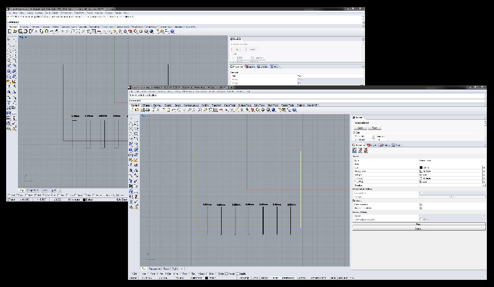
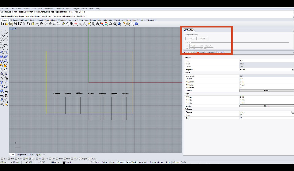
I learnt quite a bit about rhino this week like how to properly use the trimming tool and I also discovered the box edit tool, which allows you to change the sizes of objects to exact measurements.
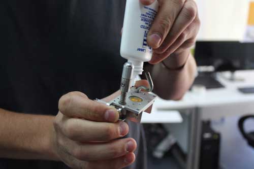
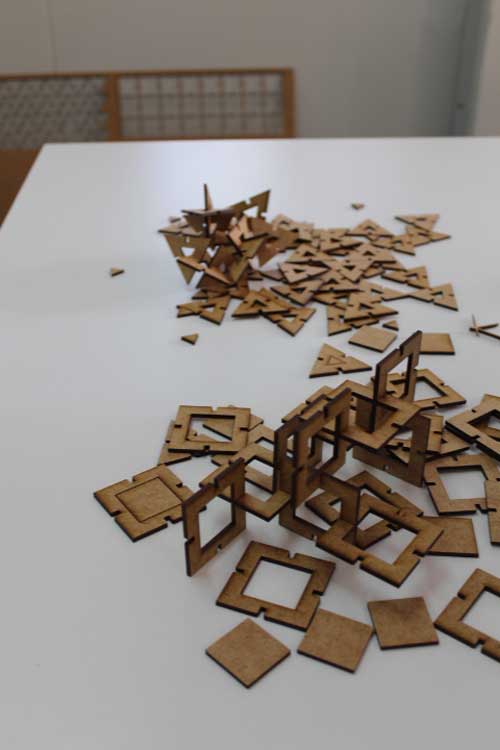
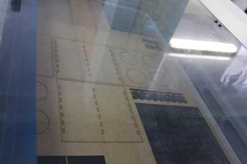
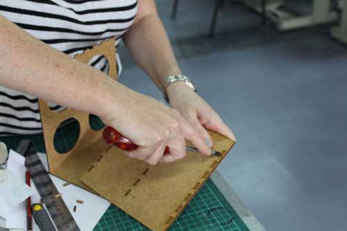
Below are pictures of the lazer cutting process I followed.
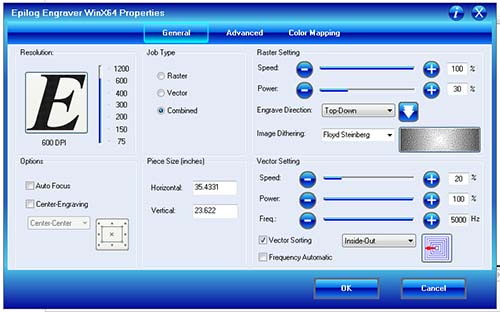
We cut our materials on the Epoilog Legend 36 EXT 60 watt machine.
First I learnt how to clean the lens. This should be done regularly, before cut set up, especially if using different materials, if it is not clean it will not focus properly and this will result in the material not being cut properly. Never touch the lens as this will damage it. When putting it back in place do not over tighten the screws.
We then went through the instruction guide and looked at the settings required for different materials.
Vector lines cut and raster lines engrave.
The vector lines need to be set to hairline for cutting.
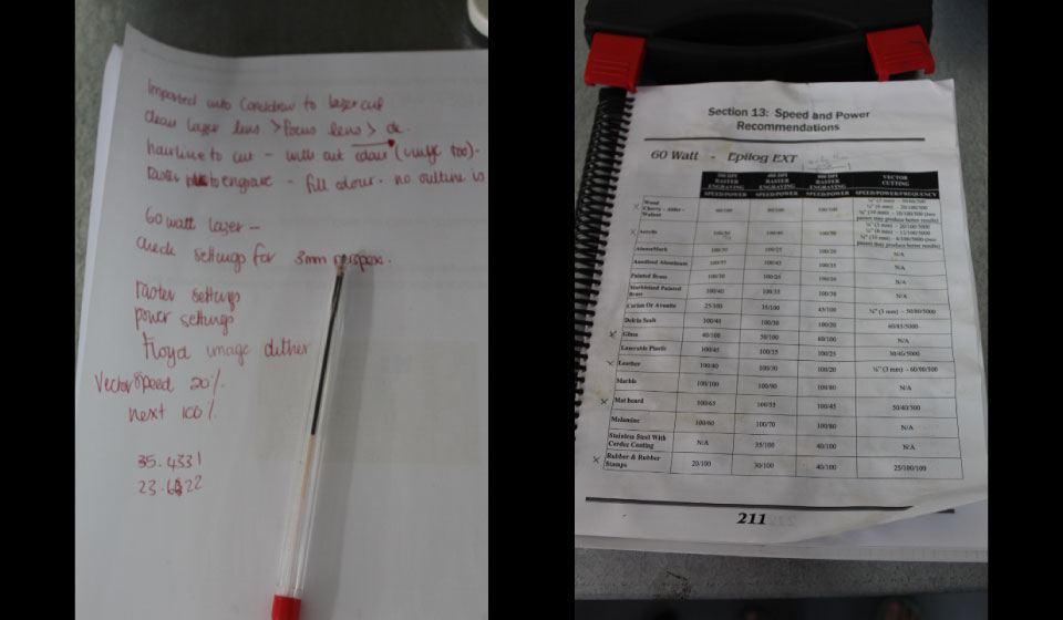
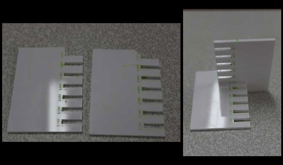
Starting with 3mm perspex, I set the machine to Acrylic;
Combined Vector and Raster, page size 35,4331" wide by 23.622" high,
using the Floyd Steinberg Image dithering setting.
Vector Cutting
20 speed
100 power
5000 frequency
Raster Engraving
100 speed
30 power
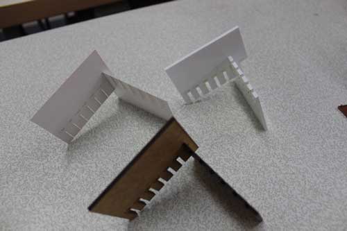
The first size (2.850mm x 2.850mm) snapped when I tested it.
My thinking is that it was because the perspex is actually slightly thicker than 3mm and perspex is less flexible, because when I tested the Chipboard, also 3mm, that was the best fit.
The second fit was slightly loose, so I would have to probably do a 2.875mm setting, that would fit perfectly.
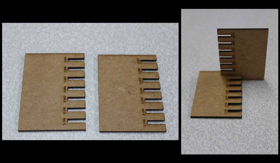
Next I cut the 3mm chipboard, I set the machine to Wood;
Combined Vector and Raster, page size 35,4331" wide by 23.622" high,
using the Floyd Steinberg Image dithering setting.
Vector Cutting
30 speed
60 power
500 frequency
Raster Engraving
100 speed
100 power
I found that the settings here were not entirely cutting through and that two cuts were required to go through the material.
The 2.85mm fit perfectly in this instance.
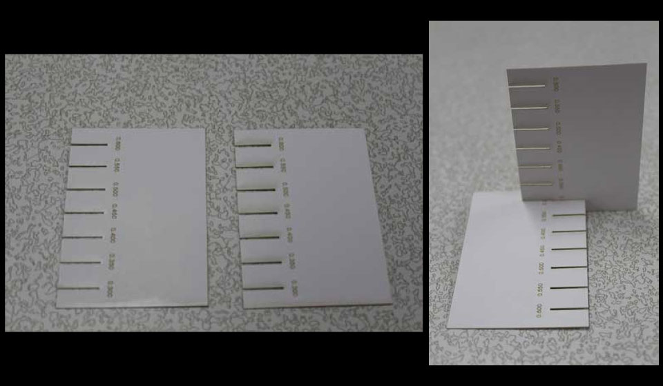
Then I cut the 0.45mm cardboard, I set the machine to Mat board;
Combined Vector and Raster, page size 35,4331" wide by 23.622" high,
using the Floyd Steinberg Image dithering setting.
Vector Cutting
50 speed
40 power
500 frequency
Raster Engraving
100 speed
45 power
The 0.300mm fit perfectly in this instance.
PARAMETRIC {PRESS/SNAP FIT}
Neil said we should try chamfering the angles for easier and better fits, I tried working in inkscape as suggested but found it very difficult to use.
Firstly figuring out how to create triangles, and then cloning the "cut sizes", the cloning definitely requires some tweaking as I found it impossible to find a way to set an anchor point in the centre so that the size was effected equally on both sides rather than, what I found, where it kept scalling from a bottom right corner. The rotated objects were even more frustarting as they did not keep shape at all.
At the rate I was designing it would be easier to make eveything from scratch each time.
I then looked at using Fusion 360, as I have been set the task to learn the programme and it seemed to have quite a good system in terms of the design, although 3D instead of 2D. I designed the system using the sketch tools, rectangle and lines.
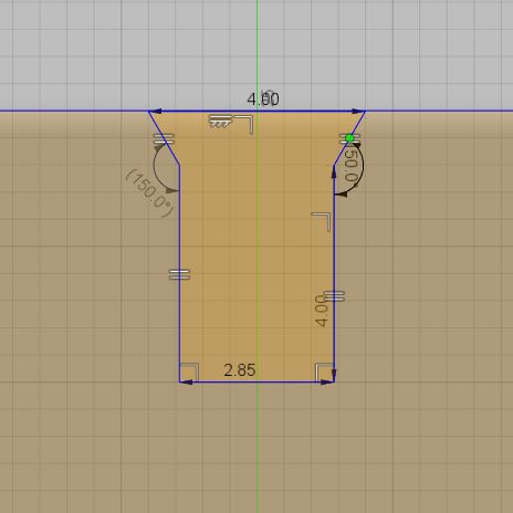
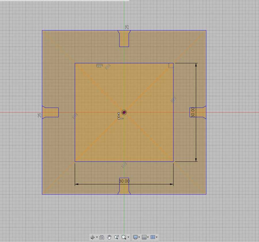
Once I had the base rectangle 50mmx50mm, I used the line tool to draw out the basic shape of the chamfered cut.
I used the sketch palette to set up constraints to ensure the accuracy of the sketch. Above you can see that I set the two vertical lines to be of equal length, and the two chamfer corner lines to be of equal length. I then set the outside angle of the chamfer for both which gave me an accurate and equal sided sketch.
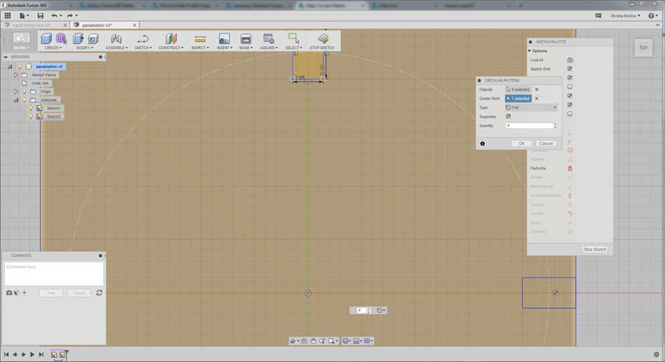
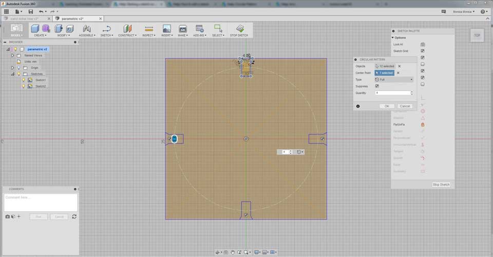
Next I used the circular pattern tool, which can be found under the sketch drop down menu, whilst you still have sketch active. From there I set the dimensions in the pattern palette. I did 3 iterations, on a full 360 degree, choosing the centre of my base rectangle as the axis.
After this I made a few changes to the initial chamfered cut rectangle, to show how the parametrics work. This was much better than the inkscape experience. I used screen shots to make the video in photoshop, apologies for the quality.
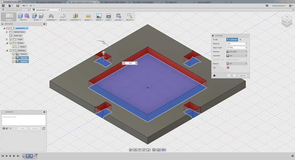
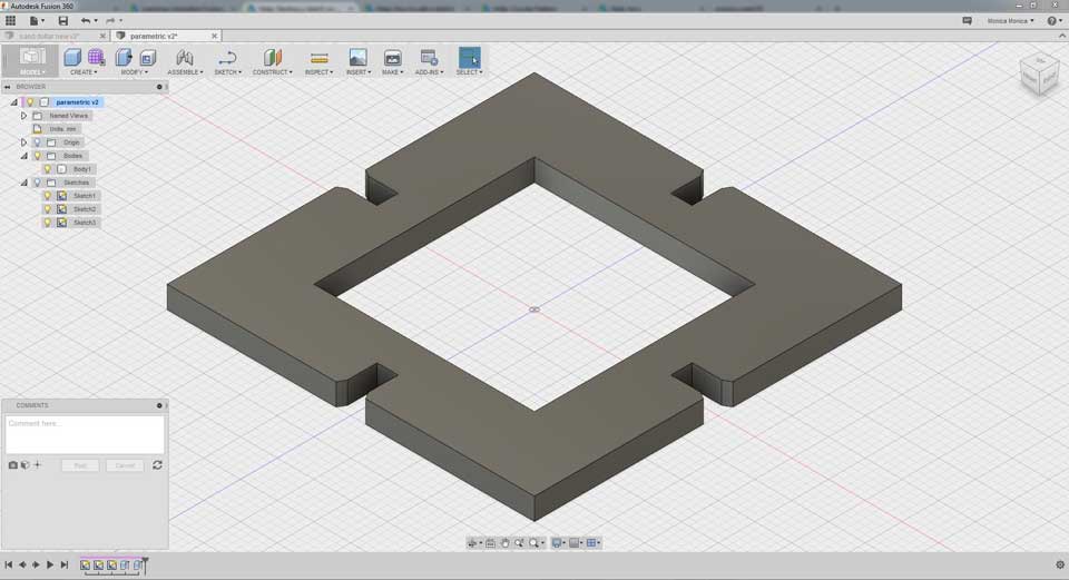
I then added a centre rectangle to the design, and extruded the shapes, to show the final 3D product.
So after this I had to try export the sketch, frustratingly I have not yet found a formatt that I could then import into coreldraw so as to be able to laser cut the design.
I tried, I screamed and I started working in illustrator, I imported one of my screen shots, made a quick sketch from that and 20 minutes later I was done.
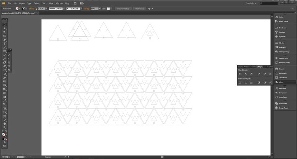
I even added a new design in the shape of a triangle.
I started with a triangle, added the square gap at the bottom so that I could align it. grouped, copied, pasted, rotated 120 degrees, pasted, rotated -120 degrees. Now I had three triangles, with the squares on each side. I center aligned them, ungrouped, deleted the unneccessary triangles and was left with just the 1 triangle and 1 square on each edge.
I used the pathfinder to bolean the shape, created a smaller triangle for the centre, to make it hollow.
Next I used the path>add points to create evenly spaced points to create the chamfer, after which I used the paths>simplify to remove any extra unneeded points.
Here you can see the progression of the triangle and the pattern ready for cutting.
We do not have cardboard currently so I will cut it either out of cardboard when we get or I may have to use the 3mm chipboard, as I have set the sizes according to the previous test fit.
I exported the file as .dxf, set the hairline for cutting. Set the printer to the desired settings;
Vector Cutting
30 speed
85 power
500 frequency
I changed the power setting and the need for two cuts was eliminated.
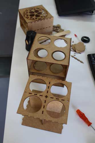
MY CONSTRUCTION KIT DESIGN {PRESS/SNAP FIT}
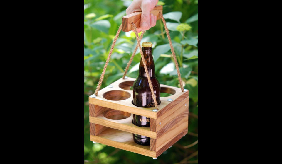
I had looked at many ways of doing press/snap fit as mentioned before and collected a folder of inspiration images. It was only when I linked the modular idea with my need of an art box that I finally decided on what I wanted to make. So I started designing my box based on an image of a beer holder I found online.
First I realised that I would be using a different type of fit construction and so I set up a file, based somewhat on sizes, estimates and the need for pressure, learnt from the previous test to see what would work.
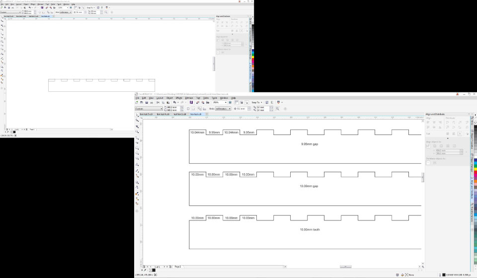
I had worked out that my box should be about 170mm x 170mm, meaning if I set up the teeth to 10mm then there would be 9 teeth and 8 gaps.
I set up the file and distributed the centre of the teeth and gaps to the 170mm size to ensure even distances.
I only needed the one toothed side, to fit in to different size gaps.
I used 10mm gaps and 9.95mm gaps.
Neither of these were very stable, pertly I think due to the depth of the material only being 3mm, so I tried a different design approach with even smaller gaps.
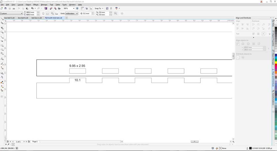
This worked quite well, with a huge improvement in stability.
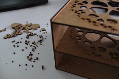
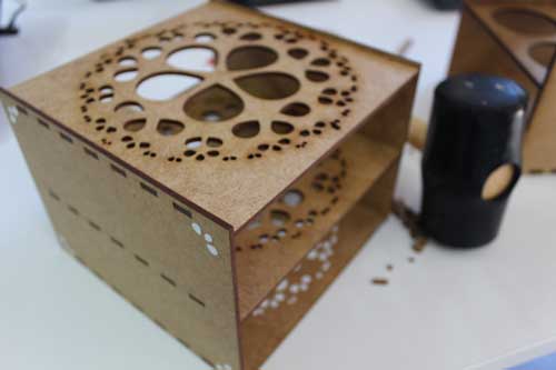
Now I started on the full design of the box construction.
I started with the idea of being to use different height sides but same middle sections, so that you can make, taller or shorter boxes depending on your needs. I also started with simple circular holes on top and after the initial design cut and worked I added a more decorative pattern, using my sand dollar artwork.
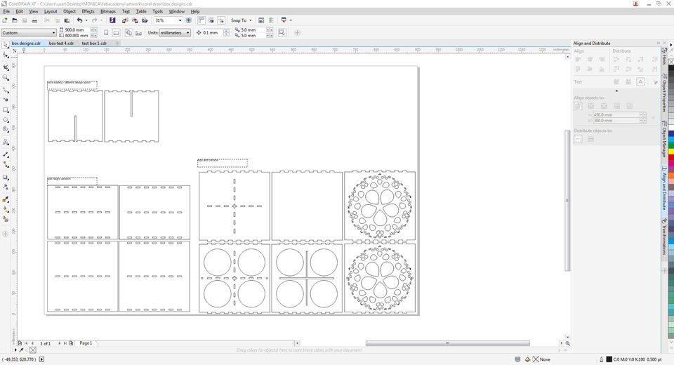
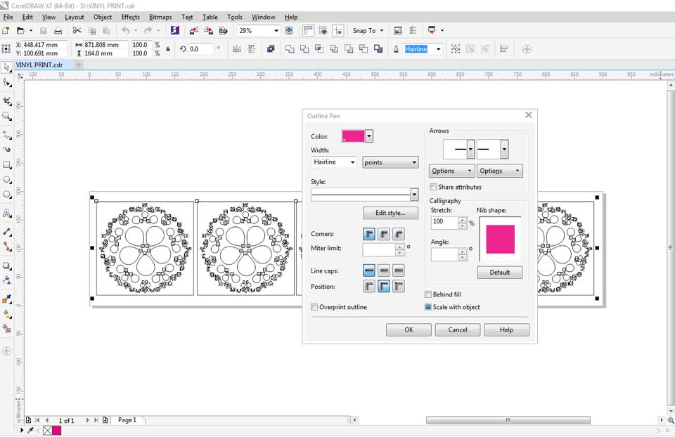
Next was the vinyl cutting. I used the same sand dollar pattern in corel draw,
added the cut colour to the hairline outline and printed it on the Roland Versa Camm.
In the Roland Versa Camm software, import the artwork.
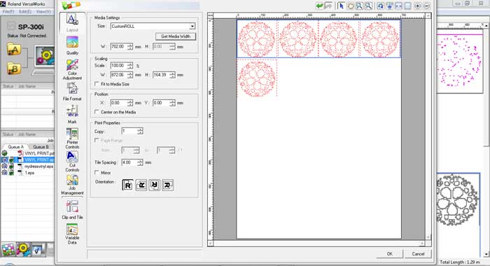
First you need to set up the printer.
Go to the settings panel and in the layout panel set the width (get media width command) of the vinyl.
Then set the quality, I used standard in this instance although no colour is required so you could set it to high speed. High quality is not required when you are only cutting vinyl.
Next set the print control to cut the sheet after output. This simply leaves the printer with a clean edge of paper. I find it slightly wasteful, but the printer does experience problems if the vinyl is not cut straight.
Lastly set the cut controls operation mode. Here I left mine on print and cut, but if you had colour that you did not want to print you could set it to cut only.
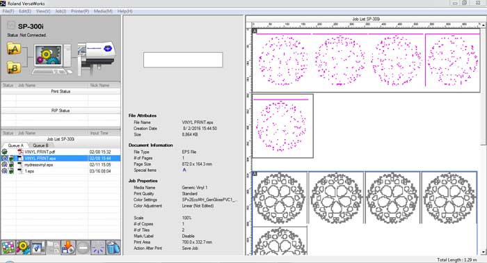
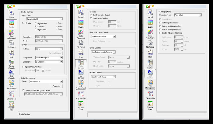
I exported a pdf first and it didn't read the colour as cut, which you can see below. I stopped the printer and used an EPS instead which worked.
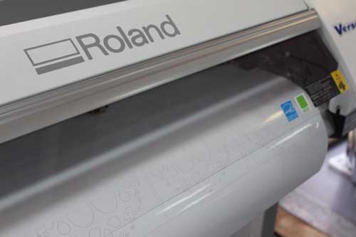
I apllied the vinyl to the bottom and sides of my box for the final product.
UPDATE {FUSION 360}
I found a way to export .dwg, from the cloud, where it stores the design files. In future I will be able to export to coreldraw.
Download my working files HERE